ENGINE REMOVAL/INSTALLATION [ZJ, Z6]
- • Fuel vapor is hazardous. It can very easily ignite, causing serious injury and damage. Always keep sparks and flames away from fuel.
- • Fuel line spills and leakage are dangerous. Fuel can ignite and cause serious injuries or death and damage. Fuel can also irritate skin and eyes. To prevent this, always complete the "Fuel Line Safety Procedure". (See BEFORE SERVICE PRECAUTION [ZJ, Z6, LF].)
1. Remove the following parts:
- (1) Battery cover, battery box, battery clamp, battery and battery tray (See BATTERY REMOVAL/INSTALLATION [ZJ, Z6].)
- (2) Front wheels and tires (See GENERAL PROCEDURES (SUSPENSION).)
- (3) Under cover and splash shields
- (4) Flesh-air duct, air hose and air cleaner component (See INTAKE-AIR SYSTEM REMOVAL/INSTALLATION [ZJ, Z6].)
- (5) Accelerator cable and bracket
- (6) Drive belt (See DRIVE BELT REPLACEMENT [ZJ, Z6].)
2. Drain the following fluids:
- (1) ATF (ATX) or transaxle oil (MTX) (See AUTOMATIC TRANSAXLE FLUID (ATF) REPLACEMENT.) (See TRANSAXLE OIL REPLACEMENT [F35M-R].)
- (2) Engine coolant (See ENGINE COOLANT REPLACEMENT [ZJ, Z6, LF].)
- (3) P/S fluid (See AIR BLEEDING.)
3. Disconnect the purge solenoid ventilation hose.
4. Disconnect the P/S return hose from the P/S oil pump side.
5. Disconnect the P/S pressure pipe from the steering gear side.
6. Disconnect the P/S return hose from the P/S reserve tank side.
7. Remove the following parts:
- (1) Member (See EXHAUST SYSTEM REMOVAL/INSTALLATION [ZJ, Z6].)
- (2) Front crossmember, front stabilizer, lower arm, steering gear and No.1 engine mount rubber component (See STEERING GEAR AND LINKAGE REMOVAL/INSTALLATION.)
- (3) Drive shaft (See DRIVE SHAFT REMOVAL/INSTALLATION.)
- (4) P/S reserve tank with the hose still connected
- (5) Coolant reserve tank with the hose still connected
- (6) Cooling fan component (See RADIATOR REMOVAL/INSTALLATION [ZJ, Z6, LF].)
- (7) ATF hose, selector cable and wiring harness (ATX) (See AUTOMATIC TRANSAXLE REMOVAL/INSTALLATION [Z6].)
- (8) Select cable and shift cable (MTX) (See MANUAL TRANSAXLE REMOVAL/INSTALLATION [F35M-R].)
- (9) Clutch release cylinder with the pipe still connected (MTX) (See CLUTCH RELEASE CYLINDER REMOVAL/INSTALLATION [F35M-R, G35M-R].)
- (10) Earth (No.3 engine mount)
- (11) The A/C compressor with the pipes still connected.
8. Disconnect the following parts:
- (1) Brake vacuum hose
- (2) Fuel hose (See QUICK RELEASE CONNECTOR REMOVAL/INSTALLATION [ZJ, Z6, LF].)
- (3) Heater hose
- (4) Upper and lower radiator hose
- (5) Main silencer (See EXHAUST SYSTEM REMOVAL/INSTALLATION [ZJ, Z6].)
9. Remove in the order indicated in the table.
10. Install in the reverse order of removal.
- • Do not tighten the No.1 engine mount rubber installation bolt before installing the No.3 engine mount. (See No.3 Engine Mount Installation Note.)
11. Inspect the following and adjust them if necessary.
- • Front wheel alignment (See FRONT WHEEL ALIGNMENT.)
- • Pulley and belt for runout and contact.
- • Leakage of engine oil, engine coolant, ATF, MT oil, and fuel.
- • Ignition timing and idle speed. Verify the amount of CO, HC. (See ENGINE TUNE-UP [ZJ, Z6].)
- • Engine-driven accessories operation
- • If the engine is overhauled and installed to the vehicle, perform the road test and verify that there is no abnormality.

|
1
|
Main fuse block connector (See Main Fuse Block Connector Removal Note.)
|
|
2
|
No.3 Engine mount (See No.3 Engine Mount, No.4 Engine Mount Rubber Removal Note.) (See No.3 Engine Mount Installation Note.)
|
|
3
|
Battery tray bracket
|
|
4
|
No.4 Engine mount rubber
|
|
5
|
Engine, transaxle
|
Main Fuse Block Connector Removal Note
1. Release the tab in the order shown in the figure.

2. Pull the lock lever up and remove the connector.
No.3 Engine Mount, No.4 Engine Mount Rubber Removal Note
1. Secure the engine and the transaxle using an engine jack and attachment.

No.4 Engine Mount Rubber Installation Note
1. Secure the engine and the transaxle using an engine jack and attachment.

2. Install the No.1 engine mount rubber and No.4 engine mount rubber.
- • Do not tighten the bolt and nut for the No.1 engine mount rubber and No.4 engine mount rubber during this step.
3. Tighten the new No.4 engine mount rubber installation bolt shown in the figure.

Tightening torque
4. Tighten the No.4 engine mount rubber and battery tray bracket installation bolt and nut in the order shown in the figure.
Tightening torque
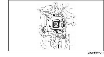
No.3 Engine Mount Installation Note
1. Tighten the No.3 engine mount installation stud bolts.

Tightening torque
2. Install the No.3 engine mount, and then temporarily tighten the installation bolts and nuts.
3. Tighten the installation bolts in the order shown in the figure.

Tightening torque
- 1 (nuts) : 44-61 N·m {4.5-6.2 kgf·m, 33-44 ft·lbf}
- 2 (bolts) : 74.5-104.9 N·m {7.60-10.70 kgf·m, 55.0-77.3 ft·lbf}
4. Remove the engine jack and attachment.
5. Tighten the No.1 engine mount rubber installation bolts.

- • Tighten the bolts in the order shown in the figure to prevent abnormal noise and vibration after assembly.