MANUAL TRANSAXLE REMOVAL/INSTALLATION [F35M-R]
1. Remove the following parts:
- (1) Battery and battery tray
- (See BATTERY REMOVAL/INSTALLATION [ZJ, Z6].)
- (2) Air cleaner component
- (See INTAKE-AIR SYSTEM REMOVAL/INSTALLATION [ZJ, Z6].)
- (3) EGR pipe
- (See EXHAUST SYSTEM REMOVAL/INSTALLATION [ZJ, Z6].)
- (4) Wheels, tires and splash shields
- (5) Under cover
- (6) Starter
- (See STARTER REMOVAL/INSTALLATION [ZJ, Z6].)
2. Drain the transaxle oil into a suitable container.
3. Remove in the order indicated in the table.
4. Install in the reverse order of removal.
5. Add the specified amount of specified transaxle oil.
- • If the transaxle is overhauled and installed to the vehicle, perform the 'INSPECTION AFTER TRANSAXLE OVERHAUL' and verify that there is no abnormality.
- (See INSPECTION AFTER TRANSAXLE OVERHAUL [F35M-R].)

.
Shift Cable and Select Cable Removal Note
1. Remove the both shift cable end and select cable end using a fastener remover.

No.4 Engine Mount Removal Note
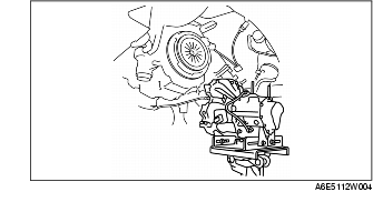
1. Remove the P/S reserve tank and coolant reserve tank with the hose still connected.
2. Using the bolts part number 99794 1025 or M10×1.25, length 25 mm {0.98 in} to install the SST to the position shown in the figure.

- • When attaching the SST in the engine rear side, install a suitable nut between the engine and the SST.

3. Insert a wood slab of appropriate size between the front fender panel and upper apron reinforcement.

4SD : approx. 35 mm {1.4 in}
5HB : approx. 60 mm {2.4 in}
4. Support the engine using the SST.

5. Remove the battery tray bracket, No.4 engine mount rubber and bracket.
Manual Transaxle Removal Note
1. Loosen the part marked A and lean the engine toward the transaxle.

2. Support the transaxle on a jack.

3. Remove the transaxle mounting bolts.
4. Remove the transaxle.
Manual Transaxle Installation Note
1. Set the transaxle on a jack and lift into place.
2. Install the transaxle mounting bolts.
3. Tighten the SST (49 E017 5A0) so that the engine is located at the specified position.
No.1 Engine Mount and No.4 Engine Mount Bracket Installation Note
1. Install the No.4 engine mount bracket on the transaxle case and tighten nuts.

2. Install the No.1 engine mount rubber to the cross member and temporarily tighten bolts.

3. Place the No.4 engine mount rubber with the body stud bolts passing through the holes and tighten the bolt in the figure.

4. Place the battery tray bracket on the No.4 Engine mount rubber with the body stud bolts passing through the holes and tighten nuts in the figure.

5. Remove the SSTs.
6. Fully tighten the bolts.

- • Tighten the bolts in the order shown in the figure to prevent abnormal noise and vibration after assembly.