FRONT SHOCK ABSORBER AND COIL SPRING REMOVAL/INSTALLATION
- • Performing the following procedures without first removing the ABS wheel-speed sensor may possibly cause an open circuit in the wiring harness if it is pulled by mistake. Before performing the following procedures, disconnect the ABS wheel-speed sensor wiring harness connector (axle side) and fix the wiring harness to an appropriate place where it will not be pulled by mistake while servicing the vehicle.
1. Remove in the order indicated in the table.
2. Install in the reverse order of removal.
3. Verify the camber and the caster are within the specification.
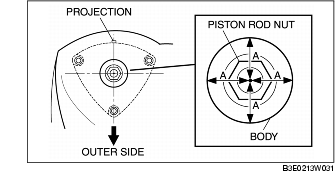
- • If they are not within the specification, align the piston rod nut with the center of the shock absorber and coil spring again. (See Shock Absorber and Coil Spring Installation Note.)
4. Inspect the total toe-in and adjust it if necessary. (See FRONT WHEEL ALIGNMENT.)

|
1
|
ABS wheel-speed sensor wiring harness connector
|
|
2
|
Brake hose
|
|
3
|
Stabilizer control link upper nut
|
|
4
|
Tie-rod end ball joint
|
|
5
|
Shock absorber lower bolt
|
|
6
|
Shock absorber upper nut
|
|
7
|
Stiffener
(See Stiffener Installation Note.)
|
|
8
|
Shock absorber and coil spring
|
|
9
|
Piston rod nut
(See Piston Rod Nut Removal Note.)
|
|
10
|
Mounting rubber
|
|
11
|
Bearing
(See Bearing Installation Note.)
|
|
12
|
Dust boot
(See Dust Boot Installation Note.)
|
|
13
|
Bound stopper
|
|
14
|
Coil spring
|
|
15
|
Front shock absorber
|
Shock Absorber and Coil Spring Removal Note
1. Loosen the front lower arm inner bolt.
2. Separate the shock absorber from the wheel hub, steering knuckle component by tapping the upper part of the steering knuckle with a hammer.

Piston Rod Nut Removal Note
- • Before removing the piston rod nut, secure the shock absorber and coil spring in the SSTs. Otherwise, the coil spring could fly off under tremendous pressure and cause serious injury or death, or damage to vehicle parts.
1. Install to the SSTs using a piece of cloth in order to prevent the coil spring from being scratched.
2. Compress the coil spring using the SSTs and remove the piston rod nut.

Coil Spring Installation Note
1. Compress the coil spring using the SSTs.

2. Install the shock absorber so that the lower end of the coil spring is seated on the step of the lower spring seat.
Dust Boot Installation Note
1. Install the dust boot by hooking the bottom edge over the shock absorber lip.

Bearing Installation Note
1. Install the bearing by hooking the upper end of the dust boot to the bearing lip.

2. Align projection A on the lower part of the shock absorber with the bearing projection B.

Shock Absorber and Coil Spring Installation Note
1. Align the piston rod nut with the center of the part where the shock absorber is installed by positioning the piston rod nut with lengths A all the same, and tighten the shock absorber upper nuts.
2. Align the knuckle notch with projection A on the lower side of the shock absorber.
3. Raise the front lower arm using a jack and install the shock absorber and coil spring.

Stiffener Installation Note
1. Install the stiffener so that the mark (RH or LH) faces upward.
