CYLINDER HEAD GASKET REPLACEMENT [LF]
- • Fuel vapor is hazardous. It can very easily ignite, causing serious injury and damage. Always keep sparks and flames away from fuel.
- • Fuel line spills and leakage are dangerous. Fuel can ignite and cause serious injuries or death and damage. Fuel can also irritate skin and eyes. To prevent this, always complete the "Fuel Line Safety Procedure". (See Fuel Line Safety Procedure.)
1. Remove the timing chain. (See TIMING CHAIN REMOVAL/INSTALLATION [LF].)
2. Remove the ignition coils. (See IGNITION COIL REMOVAL/INSTALLATION [LF].)
3. Remove the intake manifold. (See INTAKE-AIR SYSTEM REMOVAL/INSTALLATION [LF].)
4. Disconnect the following parts.
- (1) WU-TWC (See EXHAUST SYSTEM REMOVAL/INSTALLATION [LF].)
- (2) Radiator upper hose
- (3) Water hose
- (4) Heater hose
- (5) wiring harness
5. To firmly support the engine, first set the engine jack and attachment to the oil pan.

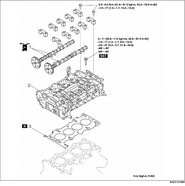
6. Remove in the order indicated in the table.
7. Install in the reverse order of removal.
8. Inspect the compression. (See COMPRESSION INSPECTION [LF].)
|
1
|
Camshaft
(See Camshaft Removal Note.)
(See Camshaft Installation Note.)
|
|
2
|
Cylinder head
(See Cylinder Head Removal Note.)
|
|
3
|
Cylinder head gasket
|
Camshaft Removal Note
- • The cylinder head and the camshaft caps are numbered to be reassembled in their original position correctly. When removed, keep the caps with the cylinder head they were removed from. Do not mix the caps.
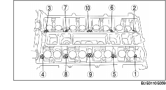
1. Loosen the camshaft cap bolts in 2-3 passes in the order shown in the figure.

Cylinder Head Removal Note
1. Loosen the cylinder head bolts in 2-3 passes in the order shown in the figure.
Cylinder Head Installation Note
1. Measure the length of each cylinder head bolt.

Length L Maximum
2. Tighten the cylinder head bolts in the order shown with the following 5 steps using the SST (49 D032 316).

Tightening torque
- (1) 3-11 N·m
- {0.4-1.1 kgf·m, 27.6-97.3 in·lbf}
- (2) 13-17 N·m
- {1.4-1.7 kgf·m, 9.59-12.5 ft·lbf}
- (3) 43-47 N·m
- {4.4-4.7 kgf·m, 31.8-34.6 ft·lbf}
- (4) 88°-92°
- (5) 88°-92°
Camshaft Installation Note
1. Set the cam position of No.1 cylinder at the top dead center (TDC) and install the camshaft.
2. Temporarily tighten the camshaft bearing caps evenly in 2-3 passes.
3. Tighten the camshaft cap bolts in the order shown with the following two steps.

Tighten torque
- (1) 5.0-8.0 N·m
- {51.0-81.5 kgf·cm, 44.3-70.8 in·lbf}
- (2) 14.0-17.0 N·m
- {1.5-1.7 kgf·m, 10.4-12.5 ft·lbf}