MANIFOLD ABSOLUTE PRESSURE (MAP) SENSOR INSPECTION [MZ-CD 1.6 (Y6)]
- • Water penetrating the connector will cause sensor malfunction. To prevent this, be careful not to damage the wiring harnesses or the waterproof connector so as to cause water penetration.
- • Before performing the following inspection, make sure to follow the procedure as indicated in the troubleshooting flowchart. (See Troubleshooting Procedure.)
Visual Inspection
1. Remove the MAP sensor. (SeeMANIFOLD ABSOLUTE PRESSURE (MAP) SENSOR REMOVAL/INSTALLATION [MZ-CD 1.6 (Y6)].)
2. Verify that there are no metal shavings on the sensor.
3. Visually inspect the MAP sensor for the following:
- • Damage
- • Cracks
- • Rusted sensor terminal
- • Bent sensor terminal
- - If there is any malfunction, replace the MAP sensor. (SeeMANIFOLD ABSOLUTE PRESSURE (MAP) SENSOR REMOVAL/INSTALLATION [MZ-CD 1.6 (Y6)].)
4. Install the MAP sensor. (SeeMANIFOLD ABSOLUTE PRESSURE (MAP) SENSOR REMOVAL/INSTALLATION [MZ-CD 1.6 (Y6)].)
Voltage Inspection
1. Turn the engine switch to the ON position (Engine off).
2. Measure the voltage between MAP sensor terminal A and body ground.

MAP sensor signal voltage (reference)
3. Start the engine.
4. Measure the voltage between MAP sensor terminal A and body ground when applying boost.

MAP sensor terminal voltage variance (reference)
5. Stop the engine.
6. Remove the MAP sensor, then connect the MAP sensor connector to the MAP sensor.
7. Connect the vacuum pump to the MAP sensor.
8. Turn the engine switch to the ON position (Engine off).
9. Measure the voltage between MAP sensor terminal A and body ground when applying vacuum.
MAP sensor terminal voltage variance (reference)Circuit Open/Short Inspection
1. Disconnect the PCM connector. (See PCM REMOVAL/INSTALLATION [MZ-CD 1.6 (Y6)].)
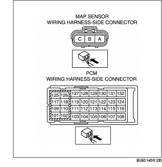
2. Inspect the following wiring harness for an open or short circuit. (Continuity check)
Open circuit
- • If there is no continuity, the circuit is open. Repair or replace the wiring harness.
- - MAP sensor terminal A and PCM terminal 234
- - MAP sensor terminal Band PCM terminal 204
- - MAP sensor terminal C and PCM terminal 205
Short circuit
- • If there is continuity, the circuit is shorted. Repair or replace the wiring harness.
- - MAP sensor terminal A and power supply.
- - MAP sensor terminal A and body ground.
- - MAP sensor terminal B and power supply.
- - MAP sensor terminal B and body ground.
- - MAP sensor terminal C and power supply.
- - MAP sensor terminal C and body ground