FUEL INJECTOR INSPECTION [ZJ, Z6, LF]
Fuel Injector Operation Inspection
- • To prevent serious injury or damage, always perform diagnosis while referring to the warnings and cautions in each procedure when inspecting or repairing the fuel system.
Fuel Cut Control Inspection
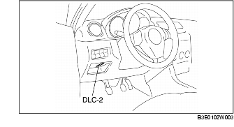
1. Connect the WDS or equivalent to the DLC-2.

2. Warm up the engine and idle it.
3. Turn off all the electrical loads and the A/C switch.
4. Using "RPM" of the PID/data monitor function, verify the engine speed.
5. Using a soundscope or a screwdriver, verify the operation sound of the fuel injector at all cylinders.
- (1) Open the throttle valve and increase the engine speed to 4,000 rpm.
- (2) Close the throttle valve instantaneously and verify that the fuel injector operation sound stops until the engine speed decreases to approx. 1,200 rpm and the sound is heard when the engine speed is approx. 1,200 rpm or less.
- • If the sound does not stop at all cylinders, inspect the following:
- • If the sound does not stop at specific cylinders, inspect the following:
- • If the operation sound stops at all cylinders but the engine speed at which the operation sound recovers is not within the specification, inspect the following:
6. Place the vehicle on a chassis dynamometer.
7. Inspect the following using the WDS or equivalent.
- (1) Verify the injector actuation time using the PID/data monitor function.
- (2) Depress the accelerator pedal and increase the engine speed to 4,000 rpm. (Loaded range)
- (3) With the accelerator pedal released (without depressing the brake pedal), verify that the injector actuation time of 0 ms is indicated until the engine speed decreases to approx. 1,200 rpm, and then the actuation time 2-5 ms is indicated when the engine speed decreases to approx. 1,000 rpm or less.
Resistance Inspection
1. Turn the ignition switch to the LOCK position.
2. Disconnect the negative battery cable.
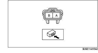
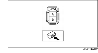
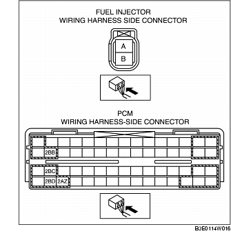
3. Disconnect the fuel injector connector.
4. Inspect the resistance between fuel injector terminals A and B using a tester.
ZJ, Z6
LF
- • If within the specification, perform the "Circuit Open/Short Inspection".
- • If not within the specification, replace the fuel injector.
Circuit Open/Short Inspection [ZJ, Z6]
1. Disconnect the PCM connector. (See PCM REMOVAL/INSTALLATION [ZJ, Z6].)
2. Inspect the following wiring harnesses for an open or short circuit (continuity check).
Open circuit
- • If there is no continuity, the circuit is open. Repair or replace the harness.
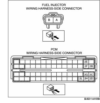
- - Fuel injector No.1 terminal A and PCM terminal 2E
- - Fuel injector No.2 terminal A and PCM terminal 2F
- - Fuel injector No.3 terminal A and PCM terminal 2G
- - Fuel injector No.4 terminal A and PCM terminal 2L
- - Fuel injector No.1 terminal B and PCM terminal 2B
- - Fuel injector No.2 terminal B and PCM terminal 2C
- - Fuel injector No.3 terminal B and PCM terminal 2D
- - Fuel injector No.4 terminal B and PCM terminal 2H
Circuit Open/Short Inspection [LF]
1. Disconnect the PCM connector. (See PCM REMOVAL/INSTALLATION [LF].)
2. Inspect the following wiring harnesses for an open or short circuit (continuity check).
Open circuit
- • If there is no continuity, the circuit is open. Repair or replace the harness.
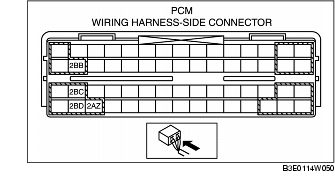
- - Fuel injector No.1 terminal A and PCM terminal 2BB
- - Fuel injector No.2 terminal A and PCM terminal 2BC
- - Fuel injector No.3 terminal A and PCM terminal 2BD
- - Fuel injector No.4 terminal A and PCM terminal 2AZ
- - Fuel injector No.1 terminal B and main relay terminal A
- - Fuel injector No.2 terminal B and main relay terminal A
- - Fuel injector No.3 terminal B and main relay terminal A
- - Fuel injector No.4 terminal B and main relay terminal A
Leakage Inspection
- • Fuel line spills and leakage from the pressurized fuel system are dangerous. Fuel can ignite and cause serious injury or death and damage. To prevent this, complete the following inspection with the engine stopped.
1. Follow "BEFORE SERVICE PRECAUTION" before performing any work operations to prevent fuel from spilling from the fuel system. (See BEFORE SERVICE PRECAUTION [ZJ, Z6, LF].)
2. Disconnect the negative battery cable.
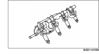
3. Remove the fuel injector and fuel distributor as a single unit. (See FUEL INJECTOR REMOVAL/INSTALLATION [LF].) (See FUEL INJECTOR REMOVAL/INSTALLATION [ZJ, Z6].)
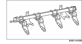
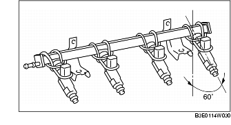
4. Fix the fuel injector to the fuel distributor with a wire or the equivalent.
ZJ, Z6
LF
5. Connect the fuel hose.
6. Connect the negative battery cable.
7. Connect the WDS or equivalent to the DLC-2.

8. Turn the ignition switch to the ON position.
9. Using the simulation function "FP", start the fuel pump.
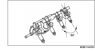
10. Tilt the fuel injector at an angle of 60° to inspect for leakage.
ZJ, Z6
LF
Standard
11. Turn the ignition switch to the LOCK position and stop the fuel pump.
12. Remove the wire or the equivalent securing the fuel injector.
13. Install the fuel injector. (See FUEL INJECTOR REMOVAL/INSTALLATION [ZJ, Z6].)(See FUEL INJECTOR REMOVAL/INSTALLATION [LF].)
14. Inspect all related parts by performing "AFTER SERVICE PRECAUTION". (See AFTER SERVICE PRECAUTION [ZJ, Z6, LF].)
Injection volume Inspection [ZJ, Z6]
- • Fuel line spills and leakage from the pressurized fuel system are dangerous. Fuel can ignite and cause serious injury or death and damage. To prevent this, complete the following inspection with the engine stopped.
1. Follow "BEFORE SERVICE PRECAUTION" before performing any work operations to prevent fuel from spilling from the fuel system. (See BEFORE SERVICE PRECAUTION [ZJ, Z6, LF].)
2. Disconnect the negative battery cable.
3. Remove the fuel injector and fuel distributor as a single unit. (See FUEL INJECTOR REMOVAL/INSTALLATION [ZJ, Z6].)
4. Fix the fuel injector to the fuel distributor with a wire or the equivalent.
5. Connect the SST to the corresponding fuel injector and battery.
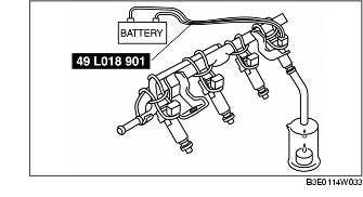
6. Connect the negative battery cable.
7. Connect the WDS or equivalent to the DLC-2.

8. Turn the ignition switch to the ON position.
9. Using the simulation function "FP", start the fuel pump.
10. Measure the fuel injection volume.
Standard11. Turn the ignition switch to the LOCK position and stop the fuel pump.
12. Remove the wire or the equivalent securing the fuel injector.
13. Install the fuel injector. (See FUEL INJECTOR REMOVAL/INSTALLATION [ZJ, Z6].)
14. Inspect all related parts by performing "AFTER SERVICE PRECAUTION". (See AFTER SERVICE PRECAUTION [ZJ, Z6, LF].)
Injection Volume Inspection [LF]
- • Fuel line spills and leakage from the pressurized fuel system are dangerous. Fuel can ignite and cause serious injury or death and damage. To prevent this, complete the following inspection with the engine stopped.
1. Follow "BEFORE SERVICE PRECAUTION" before performing any work operations to prevent fuel from spilling from the fuel system. (See BEFORE SERVICE PRECAUTION [ZJ, Z6, LF].)
2. Disconnect the negative battery cable.
3. Remove the PCM.
4. Connect the PCM connector.
5. Remove the fuel injector and fuel distributor as a single unit. (See FUEL INJECTOR REMOVAL/INSTALLATION [LF].)
6. Fix the fuel injector to the fuel distributor with a wire or the equivalent.
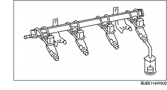
7. Connect the corresponding fuel injector connector.
8. Connect the negative battery cable.
9. Connect the WDS or equivalent to the DLC-2.
10. Turn the ignition switch to the ON position.
11. Using the simulation function "FP", start the fuel pump.
12. Ground the following PCM terminals using a jumper wire and measure the injection volume of each fuel injector.
Standard
13. Turn the ignition switch is to the LOCK position and stop the fuel pump.
14. Remove the wire or the equivalent securing the fuel injector.
15. Install the fuel injector. (See FUEL INJECTOR REMOVAL/INSTALLATION [LF].)
16. Inspect all related parts by performing "AFTER SERVICE PRECAUTION". (See AFTER SERVICE PRECAUTION [ZJ, Z6, LF].)
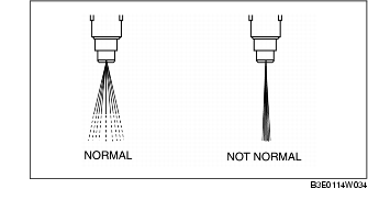
Atomization Inspection
1. Inspect the atomization status.